Here is a basic guide on how to connect gates and components.
Introduction
Read, Write, and Traces

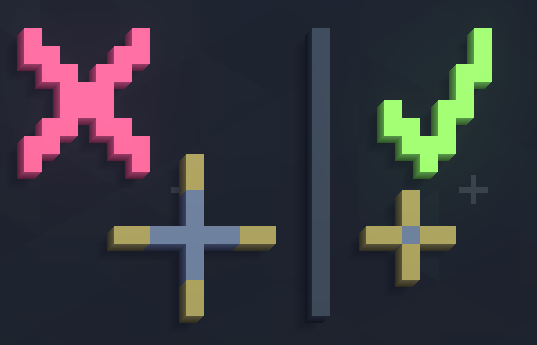
The first ink in your toolbar is the write. This ink acts as the output from logic gates and components. The next ink is trace. Trace is the wires of VCB that can interact with read, write, and cross. The third ink is cross. This allows two traces to cross each other without interacting. Note that crosses can only be one pixel wide or will not work.

The final ink is read. Read acts like the input for all of the components.

Interacting With The Simulation

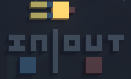
This is a latch that can be toggled on and off. Or when simulating, can act switch. Now that we have something to activate our circuit, we have to add a write to it. This is so that when we turn it on, the write will write the output of the latch onto the trace.
Now we need something to tell us if the AND gate is on. To do this we put a read to the left of the write like this.

Then, put an LED to the right of the read. Once finished all of the steps, your circuit should look like this.

Now to start the simulation, click the green button at the top of your screen that says, “Simulate”.
Summary
The discord link for VCB is https://discord.com/invite/PgBRnrE9bB
Thanks to dbomblauncher2 for his great guide, all credit to his effort. you can also read the original guide from Steam Community. enjoy the game.

