
A detailed description of the work of electrical and logical components in the game Barotrauma.
Disclaimer
Signal Types
1) Positive signal – any positive number, written either as a simple number or a number with a plus sign. Keep in mind that some components react only to 1, and any other positive number will not make them work.
2) Negative signal – written as a number with a minus sign. In this case, keep in mind that for some components it is important to have a signal, and it does not matter if it is negative or positive.
3) Signal 0 – a separate type of signal, which can be perceived as a “No” command, which, for example, leads to disconnection/closing of some components.
4) No signal – will be issued if no value is set in the string. Does not affect the values within the components, except for the component “Relay”.
Just to clarify right away that in any construction or component contact “State_Out” gives the percentage of strength of the element.
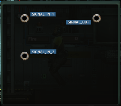
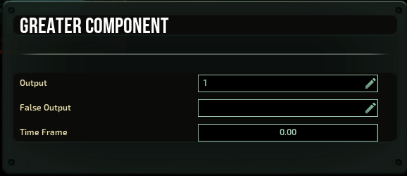
The “Greater” component

Compares the value from “Signal_In1” with the value from “Signal_In2”. If the first value is higher than the second, then the value written in “Signal_Out” is output. If the first value is less, “False Output” is output. “Time Frame” is the value of the time interval that the component will hold the value received at the input, and will compare it to the second value if it has passed no later than the set interval.
The “Not” component

If it receives a positive or negative signal – it gives 0 at the output
If it receives 0 or no signal – it gives out 1.
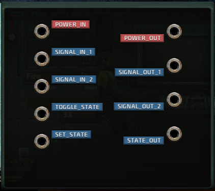
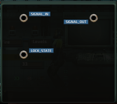
The “Relay” component

The relay does not transmit a signal from the input to the corresponding output if and only if(!) the “Toggle_State” or “Set_State” input is 0 (I could not find any difference between these inputs, also no signal or energy in any state was transmitted via the red pair “Energy_In”, “Energy_Out”). Even the absence of a signal puts the relay in the open state. The output “State_Out” gives 1 if the relay transmits a signal and 0 if not.
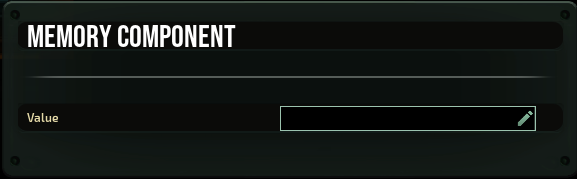
The “Memory” component

You can write a signal to the “Value” line, which will be permanently output.
If a signal is applied to the input, it will be written to the memory and therefore will be output if and only if(!) 1 is applied to the contact “Lock_State”. If 1 is continuously applied to this pin, then any value that comes to the input will be written immediately. Keep in mind that the write speed is incredibly fast (much faster than a millisecond), and if you make a counter or for some other reason, the output from this component comes directly or indirectly back to the input of the same memory component, then to adjust the speed of the value set, you should put the delay component right before the input contact, not before the “Lock_State” contact. This is how you will be able to adjust the speed of this component.
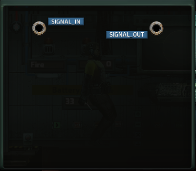
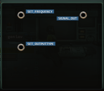
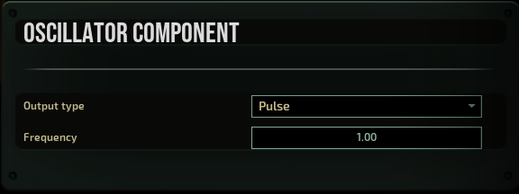
The “Oscillator” component

The “Pulse” signal defines the frequency at which the oscillator will output a signal with the value “1” and “no signal” the rest of the time. The time between the signals equals (1/ “Pulse” value), in this case the answer will be in seconds. The signal “1” itself is very short.
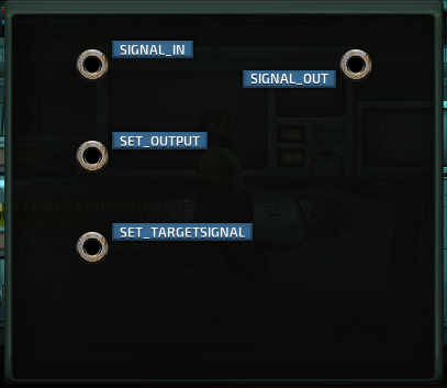
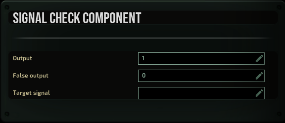
The “Signal Check” component

“Signal_In” is checked with “Target Signal” or “Set_TargetSignal”, if they coincide, the value from “Output” or “Set_Output” is output, in both cases, if values are applied to the contacts, they will change the manually entered data. If the tested signals do not match – the output will be the value from “Invalid output”.
Thanks to breakaway and Solequen for his great guide, all credit to his effort. you can also read the original guide from Steam Community. enjoy the game.
Related Posts:
- Barotrauma: Diving Guide for Beginners
- Barotrauma: How to Make Money
- Barotrauma: How to Access Ship Bank (New Colony Update Wallet System)