
Do you want to do something like switch between different video screens with the push of a button? Do you want to use buttons to select a radio frequency instead of typing a number in with a keypad? Maybe you just want to know how to use a specific logic block? Do you need to know what math and calculations you need to make a certain type of system? You might have seen something unique on the workshop, but you don’t actually know the basics of how to start making that type of system. You may have even seen a tutorial video online but didn’t quite understand it because you’re not at that level yet. I want to demonstrate some of the small tricks that I use in most of my logic circuits. Granted, I don’t make anything too crazy or complicated, but these small tricks serve as a base on which to build other types of systems.
Introduction
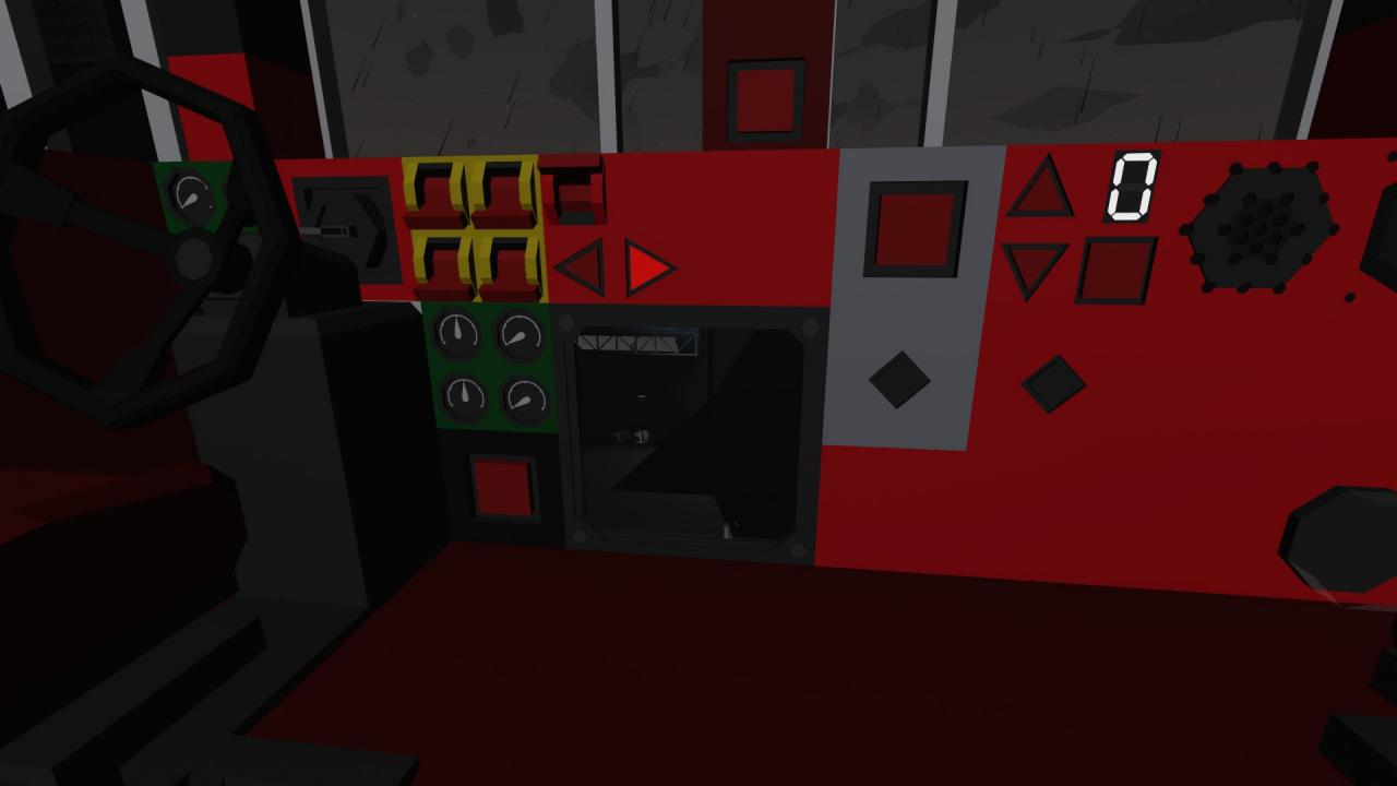
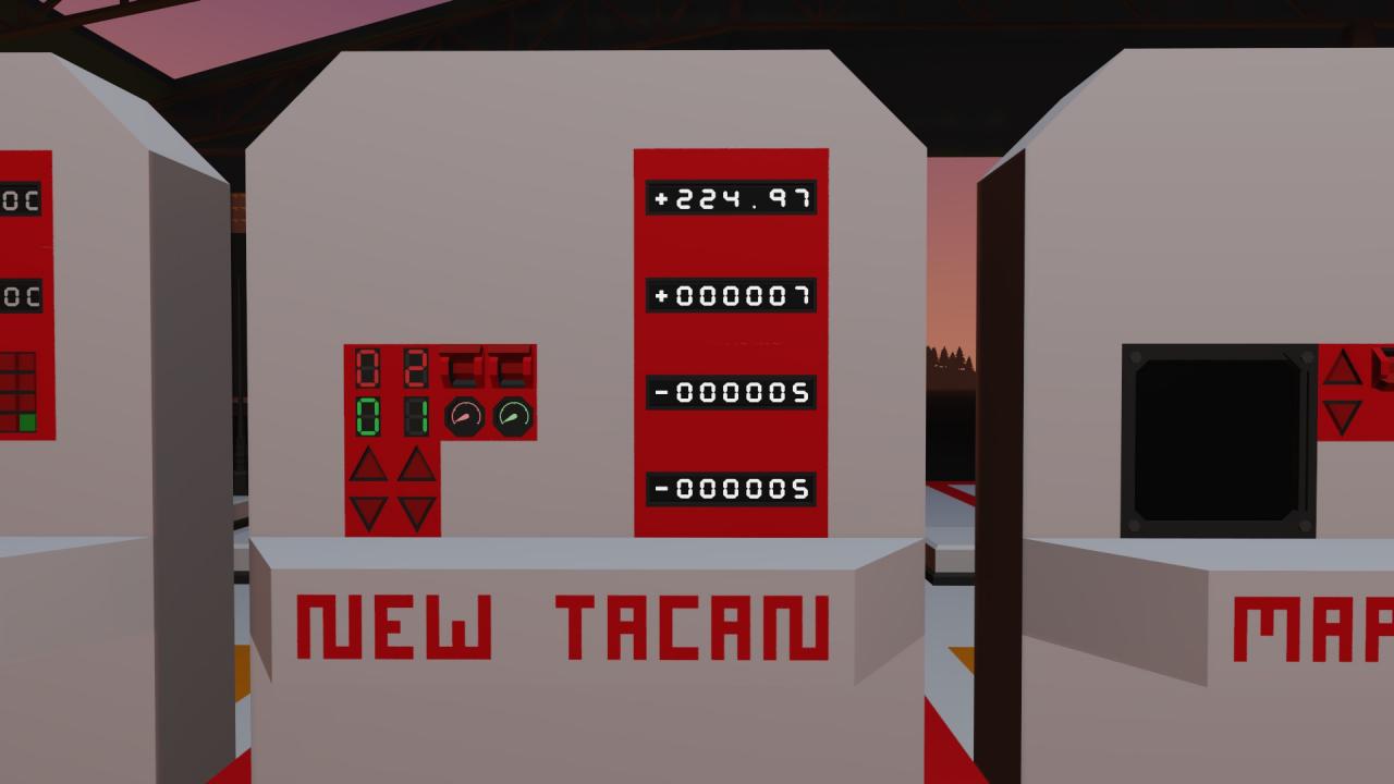
Using Buttons to Change Values on a Seven Segment Display
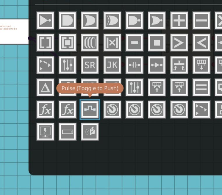
I was attempting to just connect the composite on/off signal to an up/down counter and it wasn’t working. I learned that if you just connect a push button to the counter with nothing in between the button and the counter, the counter treats it like you’re holding the button instead of just pushing it. This meant that the counter was giving me random numbers instead of simply going up and down within the set range of the counter. I found out that the trick to making it output a usable number was to have the composite-read-on/off connected to a toggle-to-push (Pulse) logic block and connect that to the counter. This gives the counter a stabilized input that it can actually use to increase or decrease the counter as required.
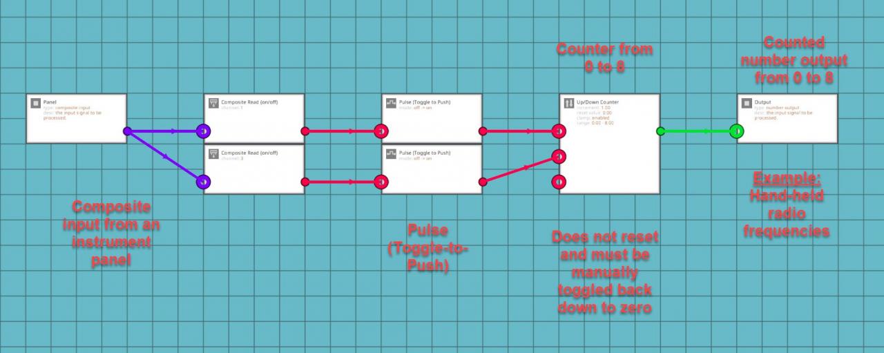
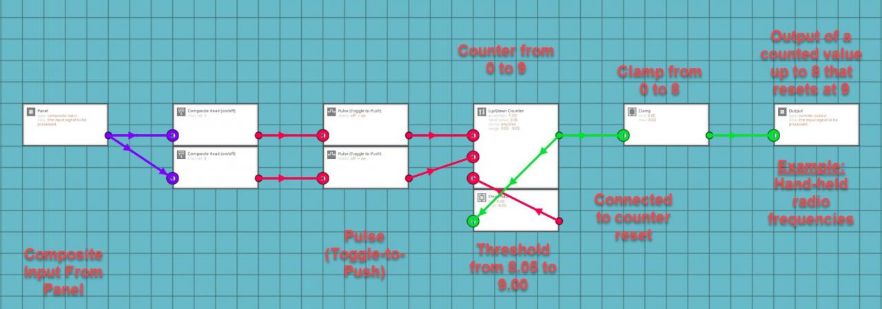
Remember to set the clamp in the counter otherwise it just increases infinitely. I later found out that you can add a threshold gate to the output, increase the clamp to one number higher than you want the display to show, set the threshold gate to half of a number higher than your determined max shown value and connect that back to the reset node for the counter.
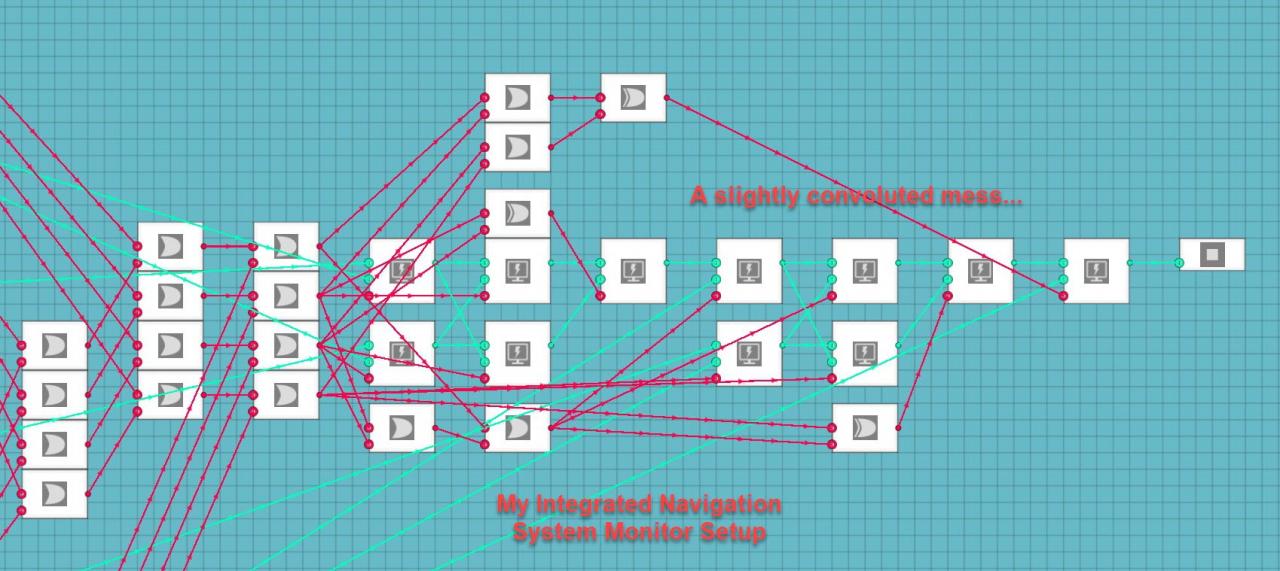
If you’re using a digital display through the LUA block, it might be useful to add a clamp to the output of the counter so that it doesn’t flash with the reset number before resetting the counter. It sounds like a trivial problem, but my integrated navigation system uses the LUA script to digitally show all of the values from all sub-systems included in the main system. These values are spaced out and need to stay within a set area or the system doesn’t look right for me. Both navigation systems in the system use 100 radio frequencies to operate ranging from 0 to 99. I have the threshold gate set to reset the counter at 100 back down to 0. I put a clamp on the output so that the screen does not show 100 as the frequency, since 100 does not really fit in my display system. The frequency doesn’t stay at 100 and it would only flash for a split second before switching to 0. I decided that I didn’t want the system to show the 100 so I clamped the output from 0 to 99. Systems using seven segment displays don’t need this clamp, but it’s still a fairly useful trick if you’re like me and don’t like arbitrary numbers that don’t mean anything flashing on your displays.
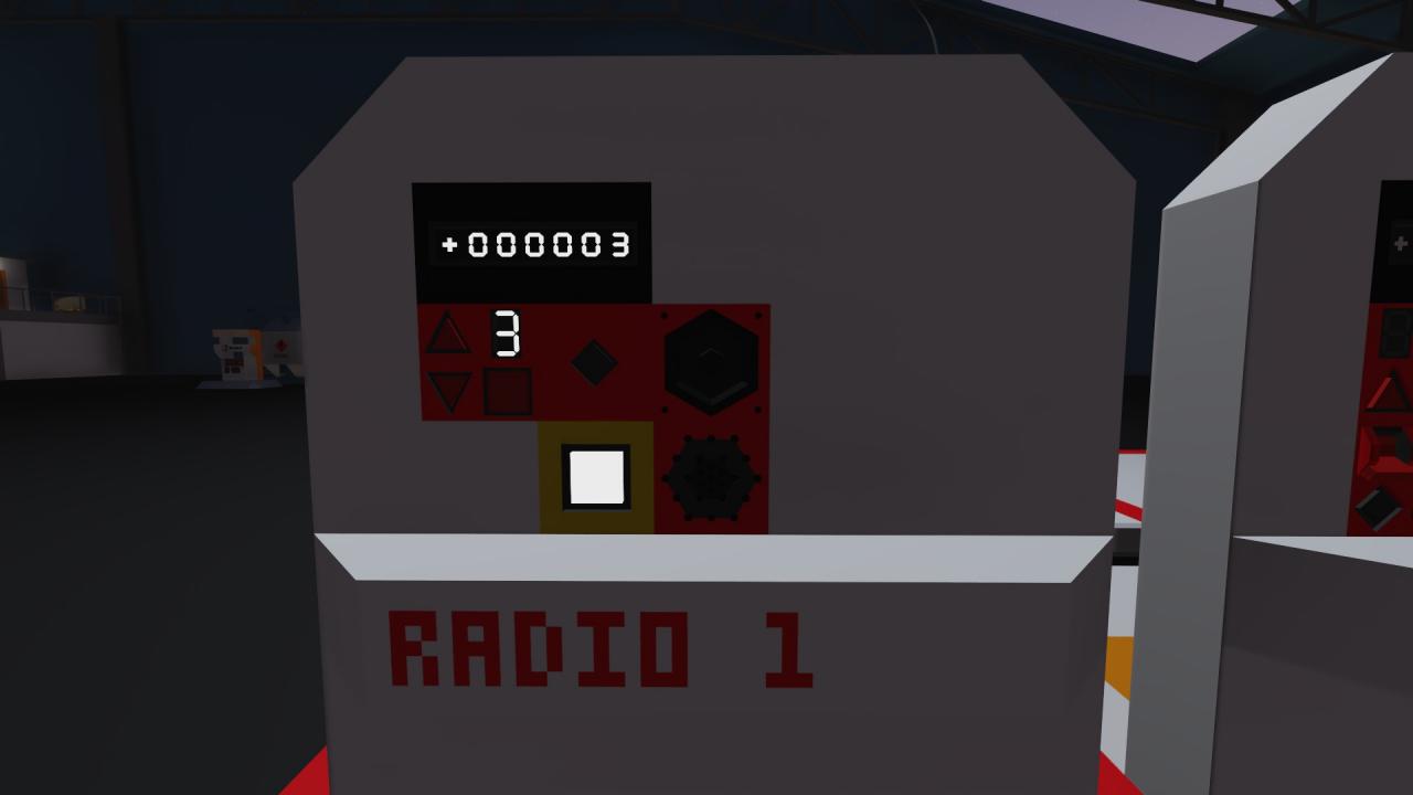
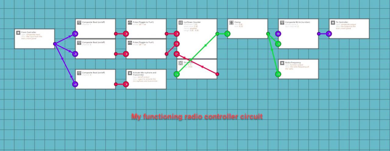
This setup is useful if you want to select radio frequencies using buttons and not a keypad. It is also useful for using buttons to zoom in and out on a map display. Connect the output from the clamp attached to the counter to the number input setting the zoom level on your LUA script for your map. This can also be used with touch screen controls. In that case, the composite input will come from your LUA script on the channel for your button on the display.
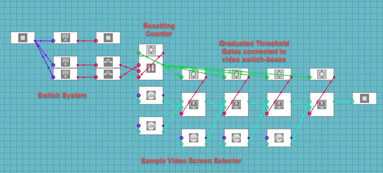
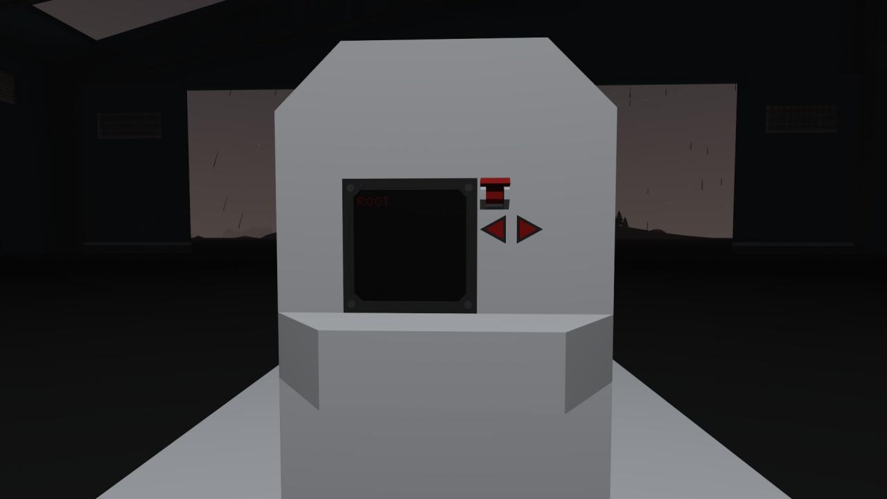
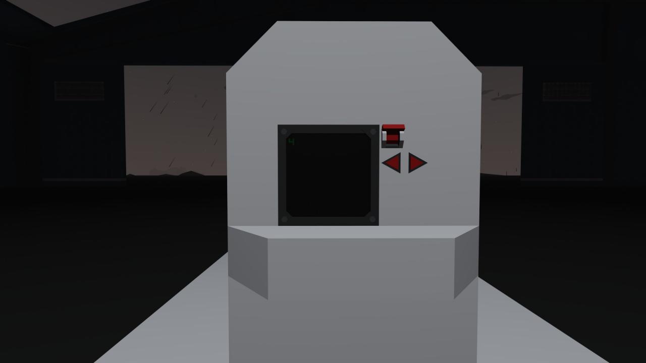
Using a Counter and Buttons to Change Displays on a Monitor
One thing that you can do is to use a counter, two buttons (either analog, digital, or touch screen), and toggle-to-push (pulse) blocks. Say you have five different video displays or menus that you want on the same monitor. Place 4 video switch-boxes in a row. Decide which screen you want to be the “Root” menu or screen and connect that video input or LUA script to the off terminal on the first switch-box. Then go down the chain of switch-boxes and put the output of the previous box into the off terminal of the next box. Get the video input signals or LUA scripts for the consecutive monitor screens connected to the on terminals of the switch-boxes in the order that you want them to be activated in. Now setup a counter circuit just like you did for the radio in the last part of the guide. Use a composite channel or on/off input connected to a toggle-to-push (pulse) logic block and connect those to the the up and down terminals of the counter. Set the clamp on the counter from 0 to 5 and then connect a threshold gate to the output of the counter. Set the threshold gate from 4.05 to 5.00 and connect the output to the reset terminal on the counter. Now grab 4 more threshold gates and place them near the video switch-boxes. Set the first gate from 1 to 1 and connect the output to the switch input for the first switch-box. Set the second gate from 2 to 2 and connect it to the second switch-box. Repeat this process for the remaining threshold gates and consecutive switch boxes. Now you should be able to toggle the counter up and down while simultaneously switching between different monitor screens.
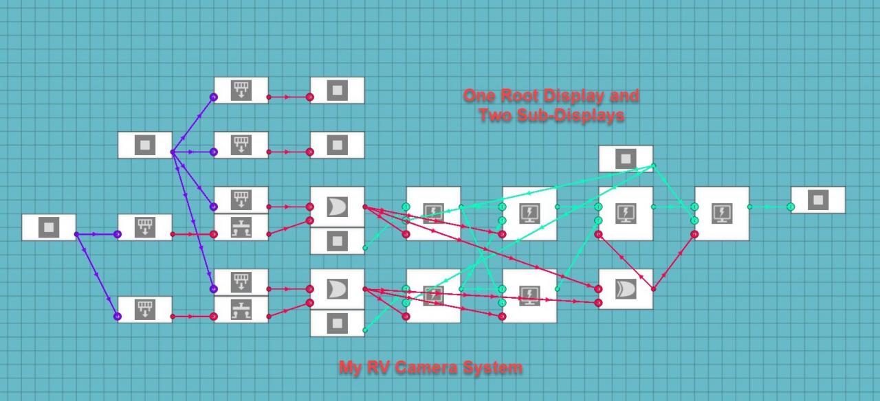
The alternative is much harder to explain and it was not a very good system to use for five separate screens. It did work for my Motorhome RV Camera system though. It only has three camera feeds connected to the controls on the console and the turn signals for the truck. Basically, you have the rear camera as the default or root screen, the side cameras can be activated with either a button on the console or the circuit for the turn signals, the side cameras are connected to an Exclusive OR (XOR) logic gate which makes it so that if both buttons are pressed the monitor returns to the root screen. It means that an XOR gate says that one or the other option can be on and the system will be on, but if both options are on the system will be off. It is much harder to scale this system up to more screens and it led to confusing results on one of my hardest systems to make.
Using Seven Segment Displays to Show Larger Numbers
This is accomplished by using a function on the number that you want to use and breaking it down into individual digits that make up the number. The function that you will use will be:
One’s Position:
floor(x/1)%10
Ten’s Position:
floor(x/10)%10
Hundred’s Position:
floor(x/100)%10
Thousand’s Position:
floor(x/1000)%10
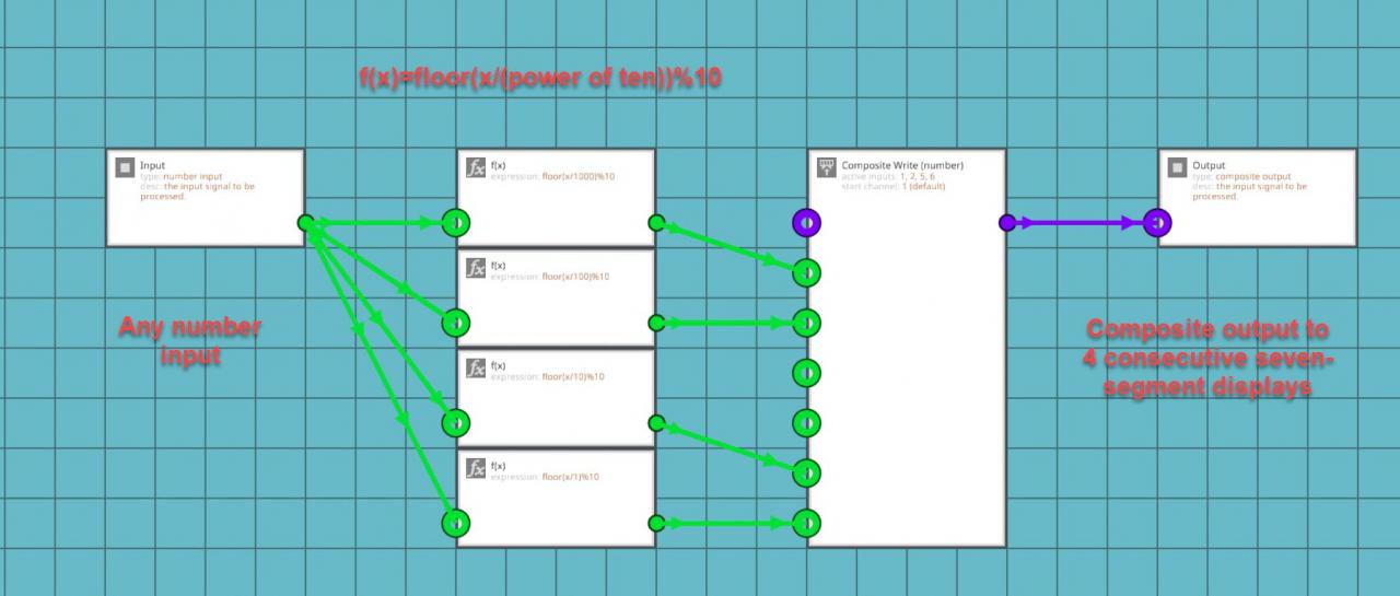
You might be wondering what these equations actually mean. It’s actually quite simple. “Floor(x)” will take your x input and round it down to the nearest whole number. It always rounds down regardless of what the actual decimal is. The “X/1” takes the the x input and finds out how many times it can be divided by 1. The number will obviously be higher than 1 but this will give you the last digit in your larger number. The “%10” added after the floor function is a modulo number in which it divides the input number and outputs the remainder. Each of these equations are applied to the same input number and then the outputs of the functions are added to composite channels corresponding with the displays on your instrument panel. For example: you have four seven-segment displays in a row on two separate instrument panels on channels 1, 2, 5, and 6. The thousand’s function will go to channel 1, the hundred’s function will go to channel 2, the ten’s function will go to channel 5, and the finally the one’s function will go to channel 6. This will allow you to show numbers from 0 to 9999 on a seven segment display. You don’t always need to show 10,000 numbers on your displays so only use the number of position equations that you actually need. Additionally, you can add more equations in intervals of powers of ten to make the display bigger than four digits.
These calculations are useful if you want to display more than single digit numbers using seven-segment displays. You can now display as many digits as you want to make displays for. It also can be applied to digital displays as well. In that case, put the composite numbers into a LUA script and recall the value on that channel to a specific place on the screen. I did this for my integrated navigation system to display the digital clock on all five screens. Separate big numbers into individual digits using these equations and put each digit on the channel of your chosen display. If you do it properly, the numbers should be displayed in order on your display system.
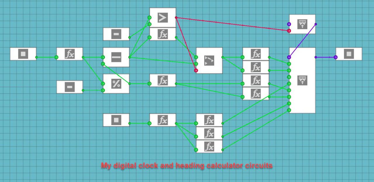
Using a Compass Sensor to Calculate the Current Heading for Your Vehicle
First you need to convert from the strange decimal number to degrees. This is done by using the following calculation:
((1-x) * 360)%360

You may have noticed that this equation has another modulo function in it. This equation means that you are subtracting the input number from the compass sensor, multiplying the difference by 360 degrees, and then performing a modulo function to output the remainder from dividing by 360 degrees. This is all that is required to convert the seemingly arbitrary number shown by the sensor into an easier to understand number you can verify with the hand-held compass. It is very important to note that the compass sensor must be placed flat, with the face pointing up and the compass arrow pointing forward on the vehicle. If it is pointing the wrong way, the calculated heading will be wrong.
Another cool thing that you can do with a similar equation is to take the direction number from a wind sensor and use an inverse function to show the direction the wind is coming from on a radial-segmented display. To do that, use the following equation:
((1+x) * 360)%360
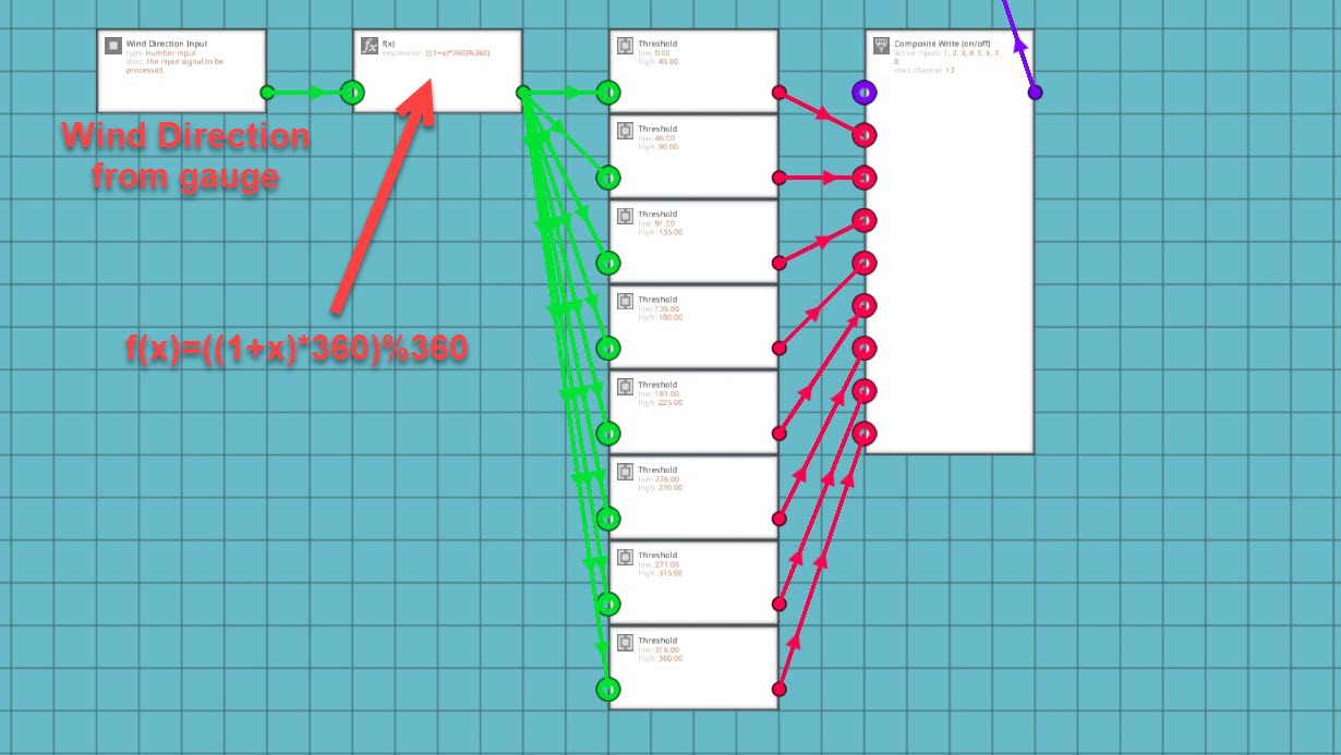
Use this equation to determine which direction the wind is coming from. Add 1 instead of subtracting from 1 to determine the direction behind the wind gauge. You can then convert the radial display to use on/off data and threshold gates for the function output in increments of 45 degrees out of 360. 0-45, 46-90, 91-135, 136-180, 181-225, 226-270, 271-315, 315-360. Remember to put the radial display on a higher frequency than the rest of your instrument panel. For my weather system, I put the radial dial on channel 13 because it needs 8 channels to display the incoming wind direction. Also, remember that this equation is used to determine which way the wind is coming from, if you want to know which way it’s blowing, just use the first equation for the heading calculations. It was more useful for me to know where the wind is coming from than where it was going so I used a back azimuth for my system.
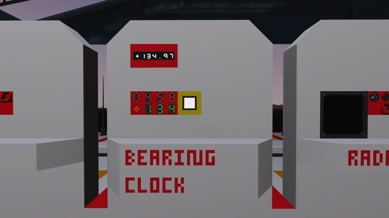
Determining the Bearing Towards a Tracked Vehicle or Grid Location
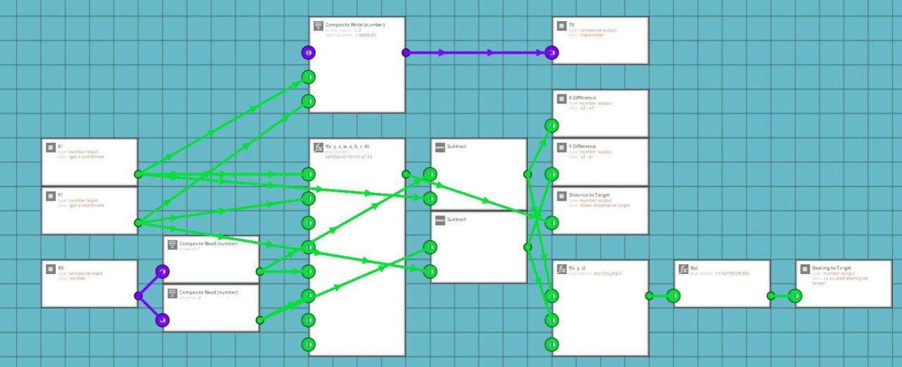
If you think back to your high school math classes, you might remember the Pythagorean Theorem (a^2 + b^2 = c^2). You will need this equation to find the linear distance to your target or how far away the point you want to reach is. First, you have to find out what A and B are in your equation. You will need a GPS Sensor to determine your current x and y coordinates (X1 and Y1) in the game world. Then take a large keypad and set a waypoint into it using the map menu. Put these coordinates into the keypad. Those coordinates will become the second x and y values. Subtract x1 from x2 and subtract y1 from y2. Plug the x difference into the x node on a three value function block. Plug the y difference into the y node on the function block. Use the following equation to calculate the linear distance to your target or destination:
sqrt((x ^ 2) + (y ^ 2))
You can also use the 8 value function block so you don’t need to separately do the subtraction. Bear in mind that you will still need the subtraction blocks for the next part of this process. The equation for the 8 value function block is as follows:
sqrt(((a – x) ^ 2) + ((b – y) ^ 2))
Now you know the straight line distance to whatever you are tracking or trying to reach. The next thing is to find out the compass bearing to that target or location. This can be used to tell your autopilot system which way the vehicle needs to be pointing to reach the plotted coordinates. I use it to determine the direction to my tracked vehicle transponder systems.
In order to determine the bearing towards your target, you will need the x and y differences between the two vehicles again. This time, you will be plugging these numbers into the x and y nodes of a different function block. The following equation will be used for the second function block:
atan2(x , y) / pi2
This uses an arctangent function to determine the angle to the target in radians. You then take the output from this function and put it into another single value function block with the following equation:
((1 + x) * 360)%360
This will convert your angle from radians to degrees
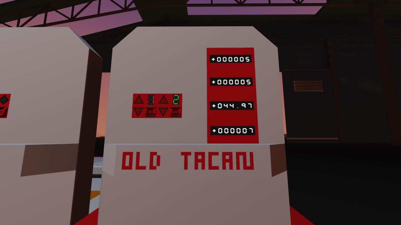
These calculations are useful for getting yourself to a chosen destination or finding a vehicle that you are tracking using something like my TACAN or IFF Transponder Systems.
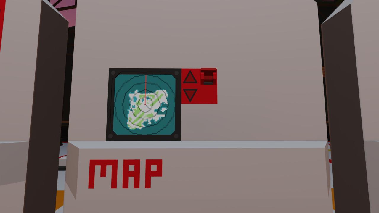
Using Calculated Bearing to Make a Digital Display or Arrow on a Map
x * (pi / 180)
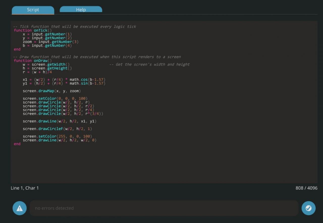
Once you convert the angle into radians, connect the output to the composite input for your LUA script. I used the variable b to represent my bearing. In the script I have variables for x, y, zoom, bearing, and the radius of my monitor display. I had to use the following code to draw a line from the center of my display point in the direction of my vehicle’s heading and going out to the radius of the first distance circle on my map:
b = input.getNumber(4)
w = screen.getWidth()
h = screen.getHeight()
r = (w + h) / 4
x1 = (w / 2) + (r / 4) * math.cos(b – 1.57)
y1 = (h / 2) + (r / 4) * math.sin(b – 1.57)
screen.drawLine(w / 2, h / 2, x1, y1)
You might be wondering what all of this means. It’s not nearly as complicated as it looks at the first glance. B is my variable and the number input from the calculated heading that was converted to radians. The screen height and width are the size of the monitor itself. The radius is for a circle that covers the whole screen from top to bottom. X1 and Y1 are using trigonometry to determine which way to draw the line. The first two parts of the equations are telling the program to find the center of the screen and then move away from the center in the direction of the calculated angle. The y portion of the graph in trigonometry is used as sine of the angle or sin(b). The x portion of the graph is used as cosine of the angle or cos(b). You have to subtract 1.57 from each angle because 0 radians starts on the positive x axis while 0 degrees starts on the positive y axis of the graph. 90 degrees converted to radians is pi / 2 radians. Pi divided by two is approximately 1.57. Alternatively, you could use (b – ((math.pi) / 2)) instead of (b – 1.57). This would be more accurate, but it also takes up more space in the script and we have limited space to write code. The line itself has x1 and y1 at the center of the screen (w / 2, h / 2) and x2 and y2 are at the x and y calculated portions of the current facing angle (X1, Y1). This might not have been the best way to label it for this tutorial, but my system does actually work.
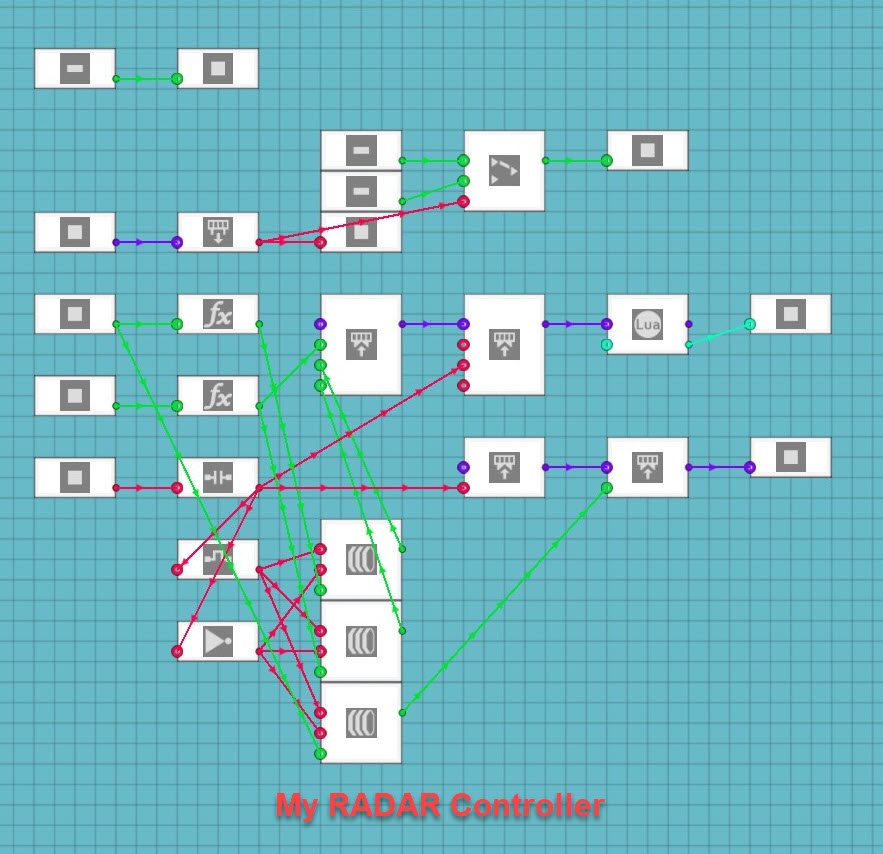
This concept can also be applied to building a functioning RADAR Display. Instead of the the angle coming from the compass sensor, the angle would come from the velocity pivot current rotation output. The following equation is used to convert the rotation angle into radians to use the angle to draw a line on the monitor:
(x * (pi / 2))
Once you go into the LUA Script, use the calculated angle in radians to tell the script where to draw the line and which way to make it point. I used an identical code for my RADAR display as I did for my map display. The only real difference is that the RADAR system has the line going to the outer circle on the display so the “R” value is just r and not (r / 4).
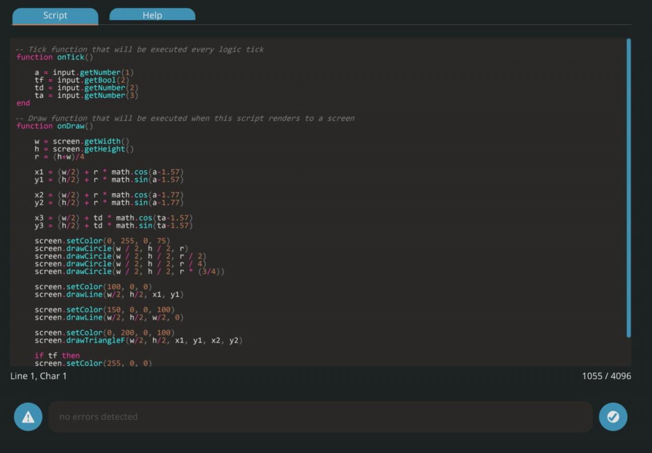
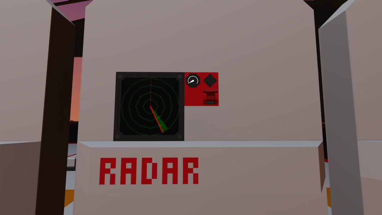
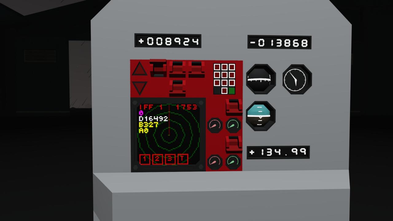
These calculations are extremely useful for a wide array of applications. I used similar calculations to make a visual “RADAR” screen for my IFF transponder to draw a dot on a screen in the direction and at a proportional distance from the receiver for a tracked vehicle transponder. These calculations simply need to be adjusted to use different numbers for their variables in the equations. My IFF system uses the “R” value as the target distance divided by the visible range on my display.
Related Posts:
- Stormworks Build and Rescue: How to make an Anchor
- Stormworks: Build and Rescue – How to Add New Cargo Terminals, Types, and Loads to the Logistics System (V1.0)
- Stormworks Build and Rescue: Ka50 Helicopter Launch and Operation Manuals
- Stormworks Build and Rescue: ow To Improve Engines For Torque
- Stormworks Build and Rescue: Types of AI Enemy Vehicles (DLC)